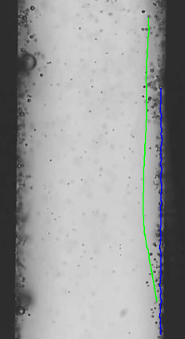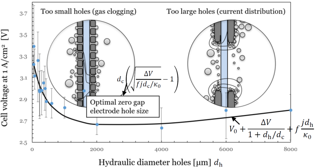
We previously demonstrated (here) that, counterintuitively, moving your electrodes further apart can sometimes decrease the ohmic resistance. A small 0.2 mm gap between a perforated electrode and the diaphragm was found to increase energy efficiency compared to a zero-gap configuration. The reason is that a small gap allows electrolyte flow and gas bubbles to escape more easily.
A natural next question is, what is the optimal value of this gap? We found that a 0.06 mm gap still gives slightly better results than a 0.2 mm gap. Smaller values are unlikely to be significantly better, since bubbles are of this size and are likely to get trapped.
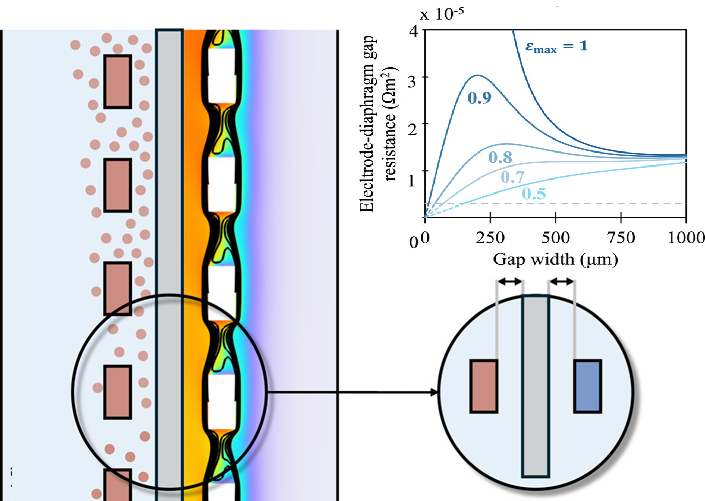
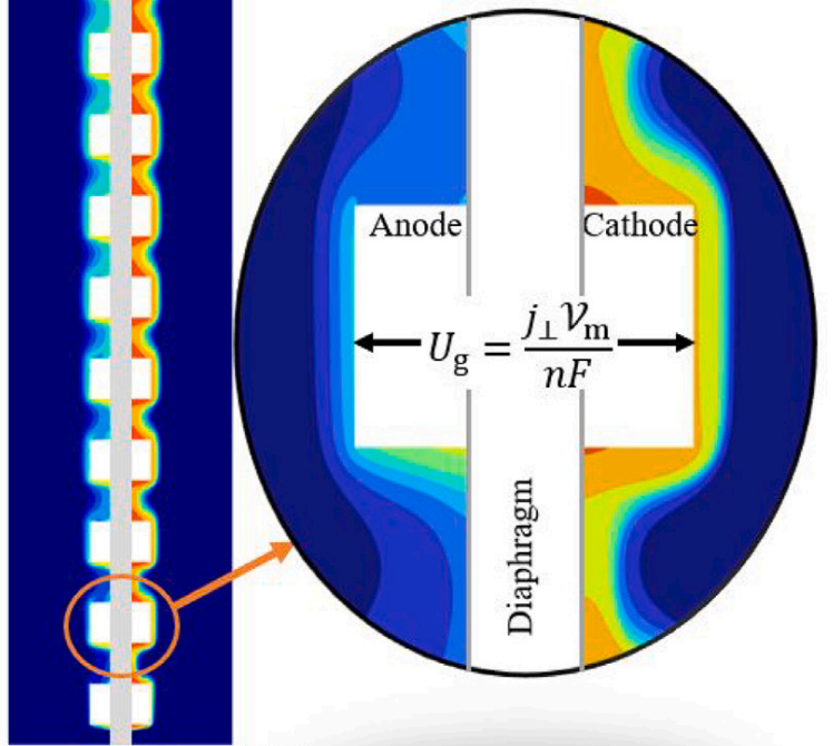
For longer distances, we found that multiphase computational fluid dynamics simulations were in good agreement with our experiments. We even developed an approximate analytical model of the gas fraction and resistance as functions of the gap distance and height. This surprisingly simple model allows for estimating how much the current density will decrease as a function of height.