How thick is the bubble layer near an electrode ?

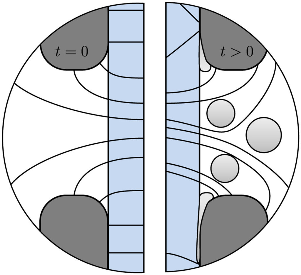
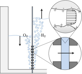
Hydrogen bubbles generated at an electrode of a water electrolyzer rise due to their buoyancy and set the surrounding liquid into motion. Alternatively, the bubbles make the mixture lighter causing it to rise – similar to the hot fluid near a heated plate. An important difference with this well-studied ‘thermal natural convection’ case is that the gas fraction has a certain maximum, below one, which influences the plume in a previously unknown way. This understanding is important, for example, to describe heat and mass transport. Knowing the bubble layer thickness is also useful to properly choose the dimensions of an electrolyzer.

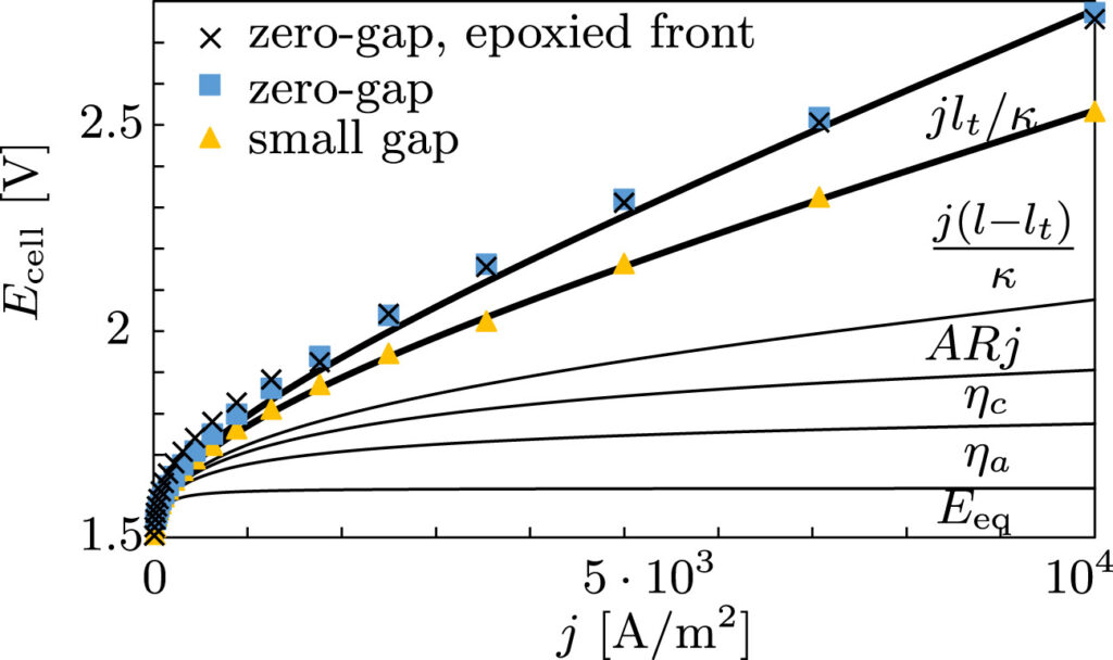
Therefore, we made an analytical model to describe the plume thickness and associated velocity profile. To validate this model, we performed computational simulations. A comparison between the analytical and computational models is shown in the below figure. The resulting formulas will be very useful for scaling up electrolyzers and understanding the effect of height and current density on gas hold-up and heat transport.

Reasonable agreement is obtained between the velocity profiles of our new analytical model (solid lines) and those of a computational mixture model (arrows).

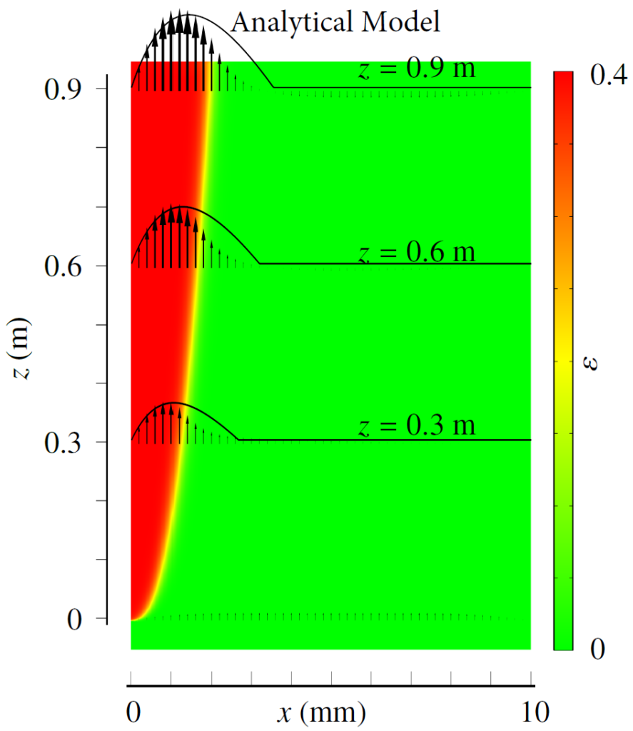
Rajora, A., & Haverkort, J. W. (2023). An analytical model for the velocity and gas fraction profiles near gas-evolving electrodes. International Journal of Hydrogen Energy.

Analytical CO2R Model

The electrochemical reduction of CO2 from flue gas, or even directly from the atmosphere, to useful products is an alluring prospect. Liquid fuels like gasoline can be made our of just air, water, and renewable electricity. One of the most promising routes is to reduce CO2 and H2O to CO and H2, or syngas. This can be done in a gas-diffusion electrode using silver catalyst particles.

In a previous post we reported on a fully analytical multiphase model of the gas-diffusion layer (GDL). Recently, we succeeded in making an analytical model of the catalyst layer (CL), including transport, electrochemical reactions and homogeneous reactions involving CO2, OH, HCO3, and CO32-.

Our publication comes with a spreadsheet you can download that implements our analytical model.

Blake, J. W., Padding, J. T., & Haverkort, J. W. (2021). Analytical modelling of CO2 reduction in gas-diffusion electrode catalyst layers. Electrochimica Acta, 138987.

Does zero-gap minimize ohmic drop?

In alkaline water electrolysers for hydrogen production, mesh electrodes are separated by a porous separator to avoid mixing of hydrogen and oxygen bubbles. Since the ohmic resistance increases with the distance over which the current travels, you would expect that minimizing the distance between the electrodes leads to the highest energy efficiency. Therefore, the so-called zero-gap configuration, in which the electrodes are placed directly adjacent to the separator, has become the standard in industrial electrolysers.

However, it has been found, time and again, that the ohmic resistance of zero-gap configurations is substantially higher than expected from the separator resistance. This can be partially attributed to the current lines not being straight in a zero-gap configuration, see the below figure. With detailed measurements we find that over the course of approximately 10 seconds the ohmic drop further increases. This can be attributed to the formation of gas bubbles, see the below figure. With this, we can now finally explain the anomalously high ohmic drops found in zero-gap water electrolysers.

Tentative current line distributions without (left) and with (right) gas (light gray) – near the separator (blue) and electrodes (dark gray).

Besides these bubble-induced losses, our detailed measurements further quantify the often-overlooked effect of dissolved gases on the equilibrium potential (Eeq in the below figure) as well as the concentration overpotential due to hydroxide depletion, only relevant at low electrolyte concentrations.

Using a small gap, the cell voltage as a function of current density j can be significantly reduced.

We also show that with a very small gap the ohmic drop can be significantly reduced, see the above figure. This initially counter-intuitive result can now be understood by the gap being large enough for bubbles to escape, allowing the current lines to become straighter. This simple and cheap way of increasing the efficiency of hydrogen production likely also leads to improved durability of the electrodes and separators as well as reduced gas cross-over. This can increase the turndown ratio, important for flexible operation of electrolysers with renewable energy.

J.W. Haverkort, H. Rajaei (2021), Voltage losses in zero-gap alkaline water electrolysis, Journal of Power Sources

Modern Diffusion Layers are Fine

Many types of fuel cells and electrolyzers contain a diffusion layer, in between the reactant flow channels and the membrane. This porous layer protects the catalyst layer and provides an electronic connection to the current collector.

To allow reactants to reach the catalyst layer by diffusion, this layer should not be too thick. Liquid products can block the pores. We needed a somewhat lengthy and analysis to show that the resulting maximum current density reads

The first part describes the well-known diffusion-limited current density. The second term describes the reduction of the limiting current due to products blocking the pores. Here jn is a characteristic current density depending on e.g. reactant viscosity and surface tension, and λ is a parameter describingthe the pore size-distribution .

The effect of the second term in this equation is usually not dominant, decreasing the limiting current by less than half. Therefore, perhaps somewhat underwhelming, the result of our mathematical exercise is that modern diffusion layers are quite well-designed. At least we now know why and under what conditions.

Rajora, A., & Haverkort, J. W. (2021). An Analytical Model for Liquid and Gas Diffusion Layers in Electrolyzers and Fuel Cells. Journal of The Electrochemical Society.

Why does the cathode level rise?

In a simple electrolysis experiment we found the cathode electrolyte level to decrease by several centimetre over the course of an hour, while that of the anode increased by a similar amount.

Since water is consumed at the cathode and produced at the anode and hydroxide ions drag still more water to the anode, this is an unexpected result. Our explanation is that the electric field, acting on positive charges near the separator pore walls, gives rise to an electro-osmotic flow from anode to cathode.

This flow impacts the limiting current as well as the crossover of dissolved hydrogen and oxygen and can therefore be useful in increasing the hydrogen purity and extending the operational range.

For more information, see:

Haverkort, J. W., & Rajaei, H. (2020). Electro-osmotic flow and the limiting current in alkaline water electrolysis. Journal of Power Sources Advances6, 100034.0034

and

Haverkort, J. W. (2020). Modeling and Experiments of Binary Electrolytes in the Presence of Diffusion, Migration, and Electro-Osmotic Flow. Physical Review Applied14(4), 044047

Is there a limiting current in alkaline water electrolysis?

Since water is the reactant in water electrolysis, you may be excused for thinking there will be no diffusion limitations. However, at the anode of an alkaline water electrolyzer the reactant is hydroxide (OH-), produced at the cathode. Although usually present at very high concentrations c0 of 6 or 7 M, these ions may deplete at the anode, leading to a limiting current density given by:

With a typical separator thickness L of 0.5 mm and effective diffusivity D of  10-9 m2/s this gives about 0.5 A/cm2, in the operating range of modern electrolyzers.

In the following graph, the measured voltage over the separator can be seen to diverge when a current larger than i0 is applied. The dashed lines show the behavior expected from a simple model.

For more information on the these measurements, the model, and their relevance for hydrogen production see:

Haverkort, J. W., & Rajaei, H. (2020). Electro-osmotic flow and the limiting current in alkaline water electrolysis. Journal of Power Sources Advances6, 100034.0034

and

Haverkort, J. W. (2020). Modeling and Experiments of Binary Electrolytes in the Presence of Diffusion, Migration, and Electro-Osmotic Flow. Physical Review Applied14(4), 044047

Compact 3D electrode designs

In many electrochemical stacks, a large fraction of the total volume goes to flow channels that transport reactants and products into and out of the cell. In the conventional bipolar ‘sandwich’ design, each flow channel borders only a single electrode. Pim van der Stighel, then a second year BSc student, in a process engineering & thermodynamics class suggested an alternative in which each electrode faces four other electrodes – sufficiently novel and promising to file a patent application together. Another team of BSc students, in co-supervision with Hadi Rajaei, made this into a metal-3D-printed prototype producing hydrogen. Our recent paper shows that electrolysers for hydrogen production can be easily made up to 1.5-2 times less voluminous, while for fuel cells or flow batteries the volume of the flow channels can even be reduced by a factor 3-4.

Worried about the practicality of making this on a large scale? A second patent was filed for a design with the same advantages, but conveniently manufactured from corrugated plate electrodes.

Patent      –    Paper

Exit ‘sandwich’ – enter ‘checkerboard’ stacks

The optimal electrode thickness

Most electrodes used in commercial applications like batteries and fuel cells contain electrodes that are porous to increase the reactive surface area. Strangely, a hitherto largely unanswered but important question is how thick such electrodes should ideally be. Thick electrodes will gives a high resistance while thin electrodes less surface area. Unsurprisingly there is an optimum, graphically shown in the below graph.

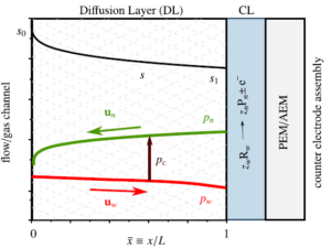
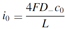
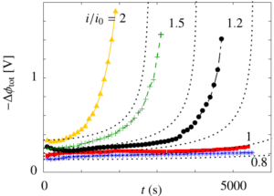
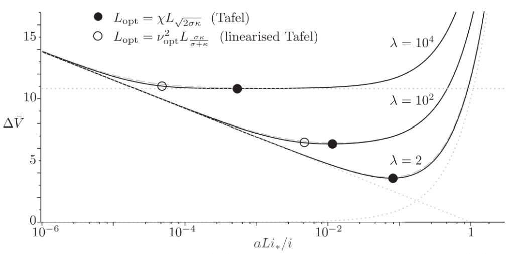
The dimensionless electrode overpotential versus electrode thickness. For the notation used see: https://doi.org/10.1016/j.electacta.2018.10.065

The seminal 1962 paper of Newman and Tobias provided exact but implicit analytical solutions. Introducing a generalization of the effectiveness factor concept, I obtained approximate explicit current-potential relations that are insightful and easy to use. Using these, analytical expressions could be derived for both the optimal electrode thickness and porosity of catalyst layers as well as battery electrodes.

A theoretical analysis of the optimal electrode thickness and porosity” can be freely accessed through: https://doi.org/10.1016/j.electacta.2018.10.065

A poster summarizing the paper presented at Modval 2019poster

A short presentation adapted from a talk at the ISE 2018 conference in Bologna or at the ECCM Conference in The Hague in 2019.

An excellent first introduction to the modeling porous electrodes can be found at:http://www.joshuagallaway.com/?p=215


Flow shear stabilizes rotating tokamak plasmas

The extremely hot plasma inside a tokamak nuclear fusion reactor ‘floats’ in a magnetic field to avoid contact with the walls. Plasma rotation has several different effects on the plasma stability, succinctly summarized in a comprehensive analytical stability criterion derived in the following publication:

Stability of localized modes in rotating tokamak plasmas
J. W. Haverkort and H. J. de Blank. Plasma Physics and Controlled Fusion, vol. 53, nr. 4, p. 045008. © 2011 DOI: 10.1088/0741-3335/53/4/045008

Besides well-known terms arising from the Kelvin-Helmholtz, magneto-rotational, and Rayleigh-Taylor instabilities, the criterion also contains two stabilizing terms due to rotation. One was described in an earlier post. Another less known effect was discovered to be due the Coriolis force also responsible for the circulating weather patterns in the earth atmosphere.

For certain conditions (See Eq. 3) the stabilizing influence of flow shear outweighs other destabilizing effects, allowing differential rotation to have a positive effect on tokamak stability.

Flow shear stabilization of rotating plasmas due to the Coriolis effect
J. W. Haverkort and H. J. de Blank. Physical Review E, vol. 86, 016411. © 2012 The American Physical Society DOI: 10.1103/PhysRevE.86.016411

Rotating tokamak plasma oscillates like atmosphere

Tokamak simulation

If you move an air parcel up in a quiet atmosphere its density will be higher than that of the air surrounding it so that it will fall back. The frequency of the resulting oscillation is called the Brunt–Väisälä frequency. The hot ionized plasma, inside the donut-shaped nuclear fusion tokamak, typically rotates around its central axis. The resulting centrifugal forces, similar to the effect of gravity, cause similar oscillations as in the atmosphere.

Through this effect rotation stabilizes and helps to keep the hot plasma confined. See also another post for a second positive effect of rotation.

The Brunt-Väisälä Frequency of Rotating Tokamak Plasmas
J. W. Haverkort, H. J. de Blank, and B. Koren

Journal of Computational Physics,
© 2012 DOI: 10.1016/j.jcp.2011.03.016