Two-dimensional, transient, yet analytical model for capacitive deionization

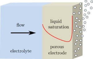
A promising way to remove low salt concentrations from brackish water is capacitive deionization (CDI). Instead of removing the water from the salt, as for example in reverse osmosis, in CDI the salt ions are removed from the water by applying an electric field. The ions are removed from the main flow and stored in the electric double layers of the porous electrodes flanking the main flow channel. Despite the fact that this is an inherently two-dimensional and transient process, usually modelled with several partial differential equations, we managed to simplify the problem to two coupled ordinary differential equations and obtained an explicit analytical solution. Here is a comparison of the salt concentration with a comprehensive computational COMSOL model:

The power of such an analytical solution lies in making optimization much easier. Instead of seven individual physical and geometrical parameters, time, and a spatial coordinate, our solution primarily depends on a single dimensionless number that is a combination of these parameters.

We find that the optimal porous electrodes are roughly six times thinner than the spacer. By minimizing the energy losses and maximizing the amount of water processed, we find that an optimal design can increase the latter metric by an order of magnitude compared to typical values in the literature.

J.W. Haverkort, B. Sanderse, J.T. Padding, and J.W. Blake (2024). An analytical
ow-by capacitive deionization mode. Desalination.

What gap and pore size maximize the energy efficiency of electrochemical flow cells?

Various electrochemical cells including microfluidic fuel cells, membraneless redox flow batteries, and microfluidic (CO2) electrolysers include a channel between their two electrodes. The wider this channel, the larger the ohmic drop. The thinner this channel, the larger the pressure drop. We obtained a simple analytical formula for the optimal channel width that minimizes the combined associated energy dissipation, which we verified using numerical simulations.

To increase surface area while avoiding diffusion limitations, sometimes porous flow-through electrodes are used. Here, a similar optimization can be performed. Smaller pore sizes give more reactive surface area, but also a larger pressure drop. Also here an analytical formula was obtained, which works well even for the popular interdigitated flow configuration.

We compared our formulas with values from various papers in the literature and found that typically an order of magnitude too large channels and pores are used. Therefore, significant improvements in energy efficiency can be obtained by further miniaturization.

The flow velocity (arrows) and reactant concentration (color) inside a repeating unit of an interdigitated flow field (left). The combined activation and pumping dissipation from simulations (diamonds) and the obtained analytical expression (solid line) along with the optimal (dashed vertical line) volumetric surface area a (roughly the inverse of pore size).

Bhadra, A., & Haverkort, J. W. (2023). The optimal electrode pore size and channel width in electrochemical flow cells. Journal of Power Sources579, 233240.

What would be the performance of a 1 m tall CO2 electrolyzer?

CO2-electrolysis is a promising way of making carbon-based fuels and chemicals from CO2, instead of from fossil fuels. Affordable electrolyzers that can efficiently convert CO2 and water into for example syngas (CO and H2) hold great promise for transforming the way carbon-based products can be industrially made in the future. There has been enormous research progress over the last few years, typically in lab set-ups with dimensions of a few centimeter. In a recent publication we tried to answer the question what would happen in a much taller electrolyzer. We find that much more of the CO2 entering the electrolyser is converted and also the fraction of the desirable CO in the outlet stream is increased. Unfortunately, our simulations show that this seemingly positive effect arises because more CO2 undergoes undesirable side-reactions with the electrolyte. As a partial remediation, we show that by varying the amount of catalyst along the electrolyzer this problem can be substantially reduced.

Joseph W. Blake, Vojtecȟ Konderla, Lorenz M. Baumgartner, David A. Vermaas, Johan T. Padding, and J. W. Haverkort, Inhomogeneities in the Catholyte Channel Limit the Upscaling of CO2 Flow Electrolysers, ACS Sustainable Chem. Eng. 2023, XXXX, XXX, XXX-XXX

What is the maximum height of a membraneless electrolyser?

Water electrolyzers without a membrane have the potential to make green hydrogen more energy efficiently and cheaper. Perhaps the simplest type of membraneless electrolyzer consists of two vertical parallel plate electrodes with upwards electrolyte flow separating hydrogen and oxygen bubbles, avoiding the formation of an explosive mixture. The faster the flow, the thinner the bubble plumes and the closer the electrodes can be placed together, resulting in a higher energy efficiency. Natural convection can only provide modest velocities. Forced flow can provide higher velocities, but to avoid turbulent mixing of the bubble plumes, these are limited to similarly modest laminar flow velocities.

A comparison of the electrolyte velocity obtained numerically (arrows) with our analytical model (solid line)

To determine how tall a membraneless electrolyzer can be made while still avoiding overlap between the oxygen and hydrogen gas plumes, we developed an analytical model that we verified with a more complete computational model and validated with experimental data from the literature. Based on our model we show that natural convection can allow safe and efficient atmospheric membraneless electrolysers up to about 5-10 cm height, while forced flow adds another 10 cm. At higher pressure, or by inducing smaller bubbles, taller or more energy efficient electrolysers of this type can be made.

Rajora, A., & Haverkort, J. W. (2022). An Analytical Multiphase Flow Model for Parallel Plate Electrolyzers. Chemical Engineering Science, 117823.

See this previous post for an alternative type of membraneless electrolyzer.

Can flow efficiently separate hydrogen from oxygen in an electrolyser?

When making hydrogen in an electrolyser, at the same time also oxygen is produced. To avoid an explosive mixture, a sub-microporous separator is placed in between the electrodes. However, this separator leads to large energy losses and allows dissolved gas to pass (see also https://jwhaverkort.weblog.tudelft.nl/?p=140).

Electrolyte flow can be used to separate all hydrogen and oxygen and make for a membraneless electrolyser.

The question is whether flow can ensure separation more energy-efficiently than a physical separator. Using a combination of modelling and experiments we found the answer to be: yes!

Placing the electrodes approximately half a millimetre apart the ohmic losses can be made much smaller than with a separator, while the pumping power adds only a small additional loss.

Rajaei, H., Rajora, A., & Haverkort, J. W. (2021). Design of membraneless gas-evolving flow-through porous electrodes. Journal of Power Sources491, 229364.

Is there a limiting current in alkaline water electrolysis?

Since water is the reactant in water electrolysis, you may be excused for thinking there will be no diffusion limitations. However, at the anode of an alkaline water electrolyzer the reactant is hydroxide (OH-), produced at the cathode. Although usually present at very high concentrations c0 of 6 or 7 M, these ions may deplete at the anode, leading to a limiting current density given by:

With a typical separator thickness L of 0.5 mm and effective diffusivity D of  10-9 m2/s this gives about 0.5 A/cm2, in the operating range of modern electrolyzers.

In the following graph, the measured voltage over the separator can be seen to diverge when a current larger than i0 is applied. The dashed lines show the behavior expected from a simple model.

For more information on the these measurements, the model, and their relevance for hydrogen production see:

Haverkort, J. W., & Rajaei, H. (2020). Electro-osmotic flow and the limiting current in alkaline water electrolysis. Journal of Power Sources Advances6, 100034.0034

and

Haverkort, J. W. (2020). Modeling and Experiments of Binary Electrolytes in the Presence of Diffusion, Migration, and Electro-Osmotic Flow. Physical Review Applied14(4), 044047

Magnetic drug targeting possible even in large arteries

Movie

By attaching drugs to magnetic nanoparticles, magnetic fields can concentrate them at the location in the body where they are needed. Pre-clinical trials have shown some potential for treatment of superficial cancer tumors. More applications could be envisioned when targets deeper in the body can be reached.

Our 2009 publication was perhaps the first three-dimensional simulation showing that it is possible to capture particles from the bloodstream of large arteries like the coronary and carotid artery. This opens up the possibility of applying the technique to combat also cardiovascular diseases.

Because of an old theorem, the drugs can only be held in a stable position deep inside the body using a dynamic magnetic field configuration or in a quasi-stable position using carefully tailored magnetic fields. Despite this fundamental complication, progress remains to be made today, particularly from the perspective of computational modeling.

Computational Simulations of Magnetic Particle Capture in Arterial Flows
J. W. Haverkort, S. Kenjeres, and C. R. Kleijn